
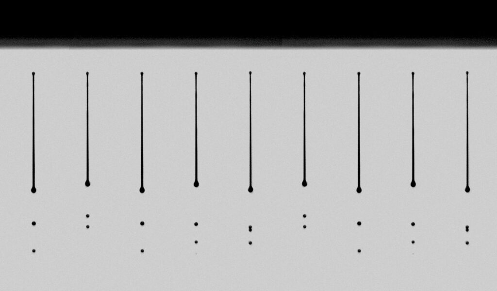
An ink and a printhead are never separately correct. A formulation that jets perfectly through one head can flood the nozzle plate, misdirect drops, or clog within a shift on another.
The variables that decide which outcome you get are rheology (viscosity and complex flow behaviours), surface tension, jetting temperature, recirculation architecture, and the drop-formation physics that ties all of them together.
If you haven’t yet settled on a chemistry, our guide to UV vs. Aqueous vs. UV-LED vs. Hybrid Inkjet Inks is worth reading first. Printhead compatibility is the next constraint once chemistry is fixed, not a substitute for it. To see the broader picture of how we approach ink development, see OEM Inkjet Ink Development.
Why Compatibility Is a Pair, Not a Property
A printhead’s viscosity specification only means something at a stated jetting temperature. Quote the number without the temperature and it tells you almost nothing, because viscosity falls as ink warms, so a formulation that sits comfortably inside the operating window at 25°C can drift well outside it at 45°C, or the reverse.
Viscosity
Most piezoelectric drop-on-demand printheads operate in a comparatively narrow band. Industry references put standard inkjet systems at roughly 2–15 cP, with individual heads publishing tighter windows once a specific chemistry and drop size are fixed. Fujifilm Dimatix Samba runs at approximately 4–8 mPa*s; StarFire specifies 8–20 mPa*s, with 10–14 recommended; Ricoh’s Gen5 and Gen6 heads both specify 10–12 mPa*s; Kyocera’s aqueous KJ4B-YH lists an optimum of 5.0–6.0 mPa*s. Xaar’s TF Technology heads sit at the other end of the range entirely, their Ultra High Viscosity work reports fluids jetted at up to 125 mPa*s in high-laydown mode, roughly ten times what a conventional head would tolerate.
Each of these is quoted at the fluid’s jetting temperature, which is why heads sometimes carry integrated heaters and thermistors: holding the ink at a fixed set point is what keeps viscosity constant across ambient swings and across a print run.
Formulators manage viscosity differently depending on chemistry. UV and UV-LED inks are built from a blend of mono- and multi-functional acrylate monomers and oligomers chosen to land in range at the head’s operating temperature, typically 40–45°C. Aqueous inks use co-solvents and humectants to tune viscosity while also protecting against evaporation at the nozzle. Solvent inks lean on high-boiling, low-evaporation solvents for the same balance.
Selected printhead specifications
| Printhead | Viscosity window | Jetting temp. | Recirculation |
| Fujifilm Dimatix Samba G3L | ~4–8 mPa*s | up to ~60°C | RediJet (nozzle) |
| Fujifilm Dimatix StarFire | 8–20 mPa*s (10–14 rec.) | up to ~50°C | RediJet (nozzle) |
| Epson Precision Core I3200-U1 | 5-7 mPa*s | ~45°C | Model dependent |
| Konica Minolta KM1800iSHK-DC | 8-12 mPa*s | Internal heater | – |
| Ricoh Gen5 / Gen6 | 10–12 mPa*s | up to 60°C | Flow-through (select models) |
| Kyocera KJ4B-YH (aqueous) | 5.0–6.0 mPa*s | internal heater | – |
| Kyocera KJ4A-EX1200-RC (2025) | 6.0-7.0 mPa*s | water-cooled | Nozzle-level |
| Xaar TF Technology (UHV) | up to ~100–125 mPa*s | ambient-capable | Full (to nozzle inlet) |
Surface Tension
Operating surface tension for inkjet inks sits in a narrow band, typically 28–35 mN/m, and it’s doing two jobs that pull in opposite directions. Inside the nozzle, surface tension has to be high enough to hold the meniscus steady between drops. Once the drop has left the nozzle, low surface tension is exactly what lets it wet and spread on the substrate rather than beading up. A formulation that’s tuned only for meniscus stability will print sharp from the head and then sit on the substrate as poorly adhered dots.
Research on this trade-off backs up the practical rule of thumb: raising surface tension from 20 to 85 mN/m in one study moved droplet breakup earlier by 18 microseconds and increased droplet velocity by roughly 56%, and higher surface tension measurably suppressed satellite formation. That’s the case for keeping surface tension toward the upper end of the range. But it only tells half the story, because surface tension measured at equilibrium isn’t the same as surface tension measured on the timescale of an actual jetting event.
Formulators increasingly look at dynamic surface tension for this reason: a surfactant needs to lower surface tension fast enough to help the drop wet the substrate within milliseconds of landing, without destabilising the jet on the way there. Getting this balance wrong shows up as satellites, flooding of the plates, or drops that print in the wrong place.
Jetting Temperature Windows
Every printhead defines an operating temperature window with a viscosity floor at one end and thermal stability at the other, and where that window sits depends entirely on chemistry. UV and aqueous inks are jetted at or only slightly above ambient, with heads typically warming the ink to somewhere in the 40–60°C range to allow for UV formulators to include higher viscosity materials and ensuring that the ink temperature is maintained despite fluctuations in ambient temperature to maintain consistent viscosity.
Printheads manage this with integrated heaters and thermistors, and some go further: patent literature on temperature compensation describes heads that store an ink’s viscosity–temperature curve and adjust drive-pulse width in real time to correct for small deviations, rather than relying on temperature control alone.
Recirculation
Recirculating architecture moves ink continuously through the fluid path, and in the best designs that flow continues right up to and immediately past the back of the nozzle itself, not just through the manifold further upstream.
Recirculation keeps particles in suspension, clears bubbles that would otherwise disrupt jetting, and holds temperature consistent across every nozzle in the array rather than letting the ones firing hardest drift warmer than their neighbours.
Several major architectures now build this in as standard rather than as a premium option: Fujifilm’s RediJet system, Xaar’s TF Technology, Toshiba Tec’s CF3 through-channel design, Seiko Instruments’ RC1536, and Kyocera’s KJ4A-EX1200-RC, launched in 2025 with nozzle-level recirculation built in from the outset.
Drop Formation and the Physics of Jettability
A piezo actuator converts a voltage waveform into a pressure wave inside the ink chamber. The positive phase of that waveform pushes ink out through the nozzle to form a ligament; the pull-back phase that follows retracts the meniscus and helps the ligament break cleanly into a single drop rather than a drop trailed by a string of smaller satellites.
Waveform design (dwell time, amplitude, the shape of the pull-back segment) has a direct and measurable effect on drop velocity, drop volume, tail length, and whether satellites form at all, which is why waveform tuning is as much a part of ink qualification as the chemistry itself.
Formulators use a handful of dimensionless numbers to screen candidate inks before committing to a jetting trial. The Ohnesorge number relates viscous forces to inertia and surface tension; its inverse, generally called the Z number, is the more commonly cited design parameter. The widely used rule of thumb places the jettable window at roughly 1 < Z < 10 — below 1, viscous dissipation prevents the drop from forming at all; above 10, satellite drops start to appear alongside the main drop.
Where Ink and Printhead Mismatch Actually Shows Up
Most of the failure modes an R&D team encounters trace back directly to one of the variables above, which makes them useful as a diagnostic starting point rather than a separate problem to solve from scratch.
Nozzle clogging usually points to particle size, dispersancy, or recirculation, oversized or unstable particles settling out, or a fluid path without enough flow to keep them suspended.
Satellite drops showing up as graininess or fine misplacement in the printed image point back to waveform tuning first, and to surface tension or viscosity second if waveform adjustment doesn’t resolve it.
Nozzle-plate flooding and drops landing in the wrong place point to a surface-tension or wetting mismatch at the plate itself, often solvable through surfactant selection rather than a full reformulation.
Kogation is specific to thermal inkjet systems, where deposits build on the heater resistor and progressively alter drop volume and velocity. Piezo heads do not have that heater-resistor failure mode, but they can still suffer nozzle fouling, plate wetting changes and deposit-related jetting instability, so ink cleanliness and long-term fluid-path compatibility remain critical.
Recirculation instability is its own category: settling or drift over the course of a full production cycle, even in a recirculating system, usually signals that the ink’s colloidal stability hasn’t been proven for long enough at the fluid’s actual operating temperature.
How Ink Suppliers and OEMs Actually Qualify a Combination
None of the above gets resolved by comparing datasheets side by side. Qualifying an ink against a printhead is an iterative process that starts with operating-window mapping, testing jetting performance across the actual range of firing frequency, temperature, and waveform the system will use in production, not just at a single nominal point.
Decap testing follows, run under pauses that reflect how the system will actually be used rather than a worst-case or best-case assumption. Recirculation stability gets checked over a complete production cycle, since a fluid that behaves well in a short test can still drift over an eight-hour run. Only once jetting performance is confirmed does testing move to adhesion and durability, crosshatch adhesion against ASTM D3359, plus whatever chemical and mechanical resistance the end application demands.
This is the work our InkDev360® programme is built around: an applied-integration team that treats ink–printhead compatibility as an engineering problem to be solved jointly, not a formulation handed over and hoped for. We work across piezo and MEMS printhead technologies from every major manufacturer, mapping the operating window for each candidate formulation and iterating with the formulation team until the ink is proven against the specific head an OEM has chosen.
A More Realistic Qualification Sequence
Start with the application constraints: substrate, image quality, productivity, curing or drying method, regulatory requirements, durability targets and the intended duty cycle. Those requirements narrow both the viable ink chemistry and the viable printhead class.
Then treat the printhead’s published viscosity, temperature, waveform and fluid-handling guidance as the initial operating envelope, not as final proof of compatibility. Formulate with margin inside the relevant limits, while accounting for the ink’s behaviour at the actual operating temperature and throughout the intended production run.
Use dimensionless screening tools such as the Z number to eliminate obviously unsuitable candidates, but do not treat them as qualification. Qualification comes from jetting trials on the selected head under realistic conditions: the intended waveform, frequency, temperature, recirculation rate, maintenance cycle and run duration.
Only once jetting remains stable across that operating window should the programme move to print performance, adhesion, curing and end-use durability testing.
Get in touch with our team to see how Fujifilm Ink can help your business.